What Happens inside a Load Cell By Tom Lily
Many years ago, I went to a venue to swap out some hoists. We had previously installed some half tonne, single phase Lodestars but they were apparently struggling. From my distant memory of the reports we were given, the clutches were slipping so must have been lifting at least 600 kg. Before we had installed the original hoists, the venue had points installed in the roof which were nicely marked with a safe working load (SWL). However, as I started installing the 1 tonne Verlindes, I realized that the SWL was 5000 N, not 5000 kg as the venue had supposed. For those that don’t know, 5000 N is actually equivalent to a little over 500 kg. This was a potentially very dangerous example of confusion over units, mass and weight.
A lot of the time, in real life, it doesn’t really matter but I think that it can help our understanding of weighing by first understanding the difference between mass and weight. I’m sure that most of us learnt it at school but never really saw the need to remember it! This shows what we are really measuring.
Mass is the amount of matter in an object and is measured in units such as kilograms (kg). Weight is the force due to gravity acting on the object, this is measured in Newtons (N). A quick approximation for weight on earth in Newtons is to multiply the mass in kilograms by 10[1]. So, a 100 kg mass has an approximate weight on earth 1000 N (really 981 N).
The point is that the mass of an object will remain the same wherever you take it. The weight will change depending on gravity. We (Mantracourt) have customers with mobile weighing devices that apply different gravity correction to their readings depending on where they are in the world. Also, technically, you shouldn’t measure non vertical force such as in bridles in units of mass such as kg. One simple way to clarify would be to refer to kilogram force (kgf) or pound force (lbf).
The simplest (and earliest) way to measure mass is to use a balance scale with other, known masses. It is effectively a comparison. If you take the whole system somewhere with lower gravity such as the moon, the mass measurement will remain the same. This technique has been around for millennia with traders using it to measure their goods. The main changes to this method over the years have been fully traceable known masses and more complex balances with moving masses. This is really just the same as a theatrical counterweight system.
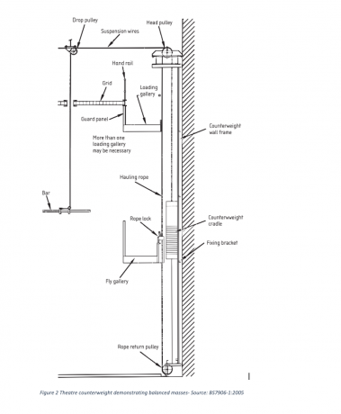
Figure 2 Theatre counterweight demonstrating balanced masses- Source: BS7906-1:2005
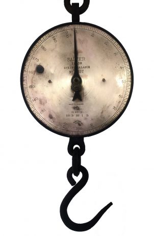
Other scales came along in the 18th century. Notably Richard Salter’s spring scale which relied on a calibrated spring extending by a linear amount as described by Robert Hooke in the previous century. Hooke’s Law basically states that (within a certain limit) a spring will extend proportionally to the force exerted on it. IE, if a weight of 10 kg extends a spring by 10 mm then a weight of 20 kg will extend the spring by 20 mm. This allowed very simple calibration of spring balances
It is also this principle that is utilized in modern load cells. On a microscopic scale, most metals behave in the same way as Hooke’s spring. They deform proportionally to the force applied to them. The engineering way to describe this is Young’s Modulus. This is a material mechanical property of stiffness. It is based on the relationship between stress and strain. Stress is the force per unit area[2] and strain is the change in length under force [3]. Using this relationship to accurately measure weight was only really possible after two inventions.
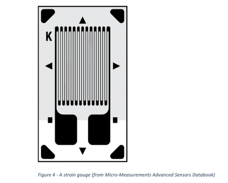
Figure 4 – A strain gauge (from Micro-Measurements Advanced Sensors Databook)
The strain gauge is a zig zag grid of very thin wire that is bonded to the metal being observed. As the metal deforms, so does the wire of the strain gauge. This deformation of the wire changes its electrical resistance by a tiny amount. This change was very difficult to measure successfully without using a Wheatstone bridge.
The Wheatstone bridge is an electronic circuit that allows very accurate comparison between resistances. A voltage is applied across two points of the bridge (the excitation voltage, VEX). The output is measured across the other two opposite points on the bridge.
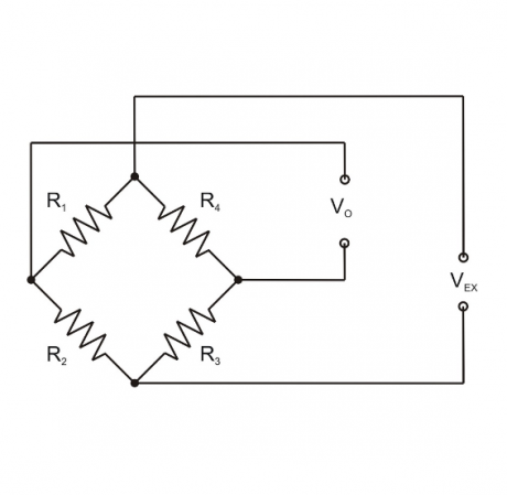
When the bridge is balanced (R1/R2= R4/ R3) the output is zero. Any deviation in resistance of the legs will result in a voltage across the output points[4]. By substituting one resistor in the bridge for a strain gauge (which is effectively a variable resistor) it is possible to measure the change in resistance of that gauge as the material that it is attached to extends and contracts. This is known as a quarter bridge. The output from this bridge is still very low and quite abstract for everyday use. To improve this output all resistors can be replaced with strain gauges and this is then known as a full bridge. Loadcell manufacturers measure the sensitivity of a load cell as the millivolt per volt (mV/V) output at full scale. This is often in the order of 2 mV/V. This is a ratio-metric measurement as the output is proportional to the input (excitation) voltage. This means that you will get the same proportional output even if the input voltage changes.
It’s not just a case of slapping four strain gauges on a piece of metal though! If you fitted them in a tension load cell as in the left of this picture (Figure 6), they would all deform the same amount, therefore the same resistances and a zero output. Therefore, the load cell manufacturer must be a little bit cleverer and would position the gauges something like the right of this picture:
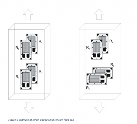
Figure 6 Example of strain gauges in a tension load cell
You can see that as tension is applied to the right hand load cell the long sides of R1 and R3 are compressed, lowering the resistance. The long side of R2 and R4 is extended, increasing the resistance. This setup gives approximately four times the output of a quarter bridge. Similar techniques are used in other types of load cells. In some instances, it is also possible to cancel out measurements that you are not interested in such as torsion.
Another, more obvious technique, is the use of stress raisers. In most structural engineering design, these are to be avoided as they have been the cause of catastrophic failures in the past[5]. There is no problem when carefully designed and tested. These will take different forms depending on the type of load cell. This is very easy to see in the case of a shackle type load cell.
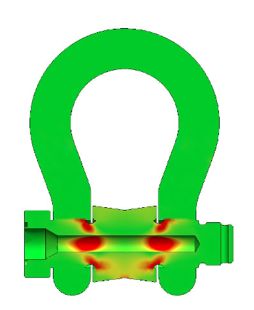
Figure 7 Finite element analysis of load pin with stress concentrators
In this figure of a load pin finite element analysis, the red areas are the positions of highest strain. This shows the effect of the stress concentrators on the strain in the pin. We can also instantly see the obvious places to put our strain gauges! These need to be carefully glued to the base material. As we can see, in a shackle type load cell the most sophisticated (and expensive) part is the pin[6]. The Wheatstone bridge output from the four gauges inside the pin still isn’t very useful for a rigger.
This is where signal conditioning comes in. We now need some electronics to make this into something useful. There are three main types of output from a load cell signal conditioner.
Analogue. This is tried and tested technology that has been around for a long time. Analogue output is either voltage or current based with the most popular being 0-10 V and 4-20 mA. 0-10 V can be marginally cheaper and simpler but is more susceptible to noise, especially over long cable runs. Another significant advantage that 4-20 mA has is that its zero (or low) point is at 4 mA. If the voltage output fails, it will show zero volts or minimum load, if the current output fails it will show zero milliamps which can be easily detected as an error. Analogue is a one to one system though so requires a lot of cabling for large systems.
Digital- cabled. This is where we can start to monitor more complex, multi-cell systems. Different load cell manufacturers use different protocols. Probably the most popular is Modbus transmitted over an RS485 bus. A good bus system will minimise cabling as you can daisy-chain the loadcells in a line. Different manufacturers will set different limits to the amount of load cells in a run which will depend on the update rates of the load cells and the power required to run them. The biggest problem with digital cabled systems is that if you lose a connection, all load cells downstream of that will be lost.
Digital- wireless. The signal conditioner encodes the load cell weight data into a digital signal that can then be transmitted via radio. Again, different manufacturers use different frequencies and techniques down to their own expertise and preference. The company I work for, Broadweigh, use our own protocol transmitting in the 2.4 GHz frequency band. This is a useful band to work in as it has very similar rules all over the world. The rules allow a great deal of radio traffic to coexist on the same radio frequency. (There is a lot more to this but it may be for another time).
All the above methods then need some form of receiving device. More detail on that is probably for another article. These can vary from handheld displays showing data from one load cell to PCs displaying and logging data from tens or hundreds of load cells.
Returning to my original story, slipping clutches often used to be the first warning that there was something wrong with the calculations. Twenty years ago, the load cells that were available were not geared towards the entertainment market. At that time, I think that I had used load cells twice on jobs that I was involved in. These were for balancing a very tricky truss in a tension tent and weighing a stripped-down harrier jump jet. These were large analogue load links which were one to one with a nasty thin, stiff cable that was constantly tangling itself up.
Since then, companies have started to cater for the entertainment industry. One to one wired systems have developed into digital wired and wireless systems where multiple load cells can now all be monitored on a single computer. With these improvements there are less and less excuses for not really knowing what the loads in a system are.
Tom Lilly started in the entertainment industry over 25 years ago carrying speakers and amplifiers upstairs for a small PA company in Birmingham. Whilst working in a hire warehouse in Bristol he developed an interest in rigging and managed to pick up some good experience. A few years later he started working as a freelance rigger. He had a hiatus from the entertainment industry for about five years where he was first a greenkeeper and then helped run a pub! In 2010 Tom started an Open University engineering degree which he graduated with honours in 2016. During that time, he started work at Mantracourt Electronics a leading electronics company specializing in signal conditioners. Mantracourt Electronics are also the designers and manufacturers of the Broadweigh Load Monitoring System for Live Events.
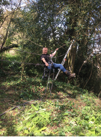
Figure 8 Tom Lilly, Rigger and Applications Engineer at Broadweigh
Figure 2 Theatre counterweight demonstrating balanced masses- Source: BS7906-1:2005
Figure 4 – A strain gauge (from Micro-Measurements Advanced Sensors Databook)
Figure 6 Example of strain gauges in a tension load cell
Figure 7 Finite element analysis of load pin with stress concentrators
Figure 8 Tom Lilly, Rigger and Applications Engineer at Broadweigh
[1] This is derived from Newton’s second law of motion which shows the relationship between force, mass and acceleration on an object. Simply, F=ma. To calculate weight, the mass is multiplied by the acceleration due to gravity which is 9.81 metres per second squared.
[2] A rod loaded in tension to 100 N with a cross-sectional area of 100 mm2 would experience the same stress (1 N/mm2) as a rod loaded to 200 N with a cross-sectional area of 200 mm2.
[3] Strain is calculated by dividing the change in length by the original length which gives a dimensionless result. A one metre rod that extends by 0.0001 metres under load would have a strain of 0.0001. To simplify this, it is often shown as a percentage (0.01% strain) or in terms of microstrain (100 microstrain). The strain at full scale in Broadweigh load cells is approximately 1100 microstrain.
[4] The Wheatstone bridge is often also used for measuring an unknown resistance. If you accurately know the other three resistors in the bridge and the voltage input and output, it is possible to calculate the value of the other resistor.
[5] Probably most notably the Liberty ships built in the second world war. Nineteen of these ships broke in half with very little warning. Around 1500 showed other signs of brittle failure. One of the causes was where square hatch corners coincided with weld points that caused stress concentration and cracks to rapidly grow from that point. It also happened that the hulls were welded instead of rivetted, so the cracks propagated very quickly with nothing to stop them.
[6] People often forget just how sensitive load cells are. They are very sensitive, expensive pieces of measuring equipment and need to be treated with respect.